CSOUND
SUBTRACTIVE SYNTHESIS
Introduction
Subtractive synthesis is, at least conceptually, the inverse of additive synthesis in that instead of building complex sound through the addition of simple cellular materials such as sine waves, subtractive synthesis begins with a complex sound source, such as white noise or a recorded sample, or a rich waveform, such as a sawtooth or pulse, and proceeds to refine that sound by removing partials or entire sections of the frequency spectrum through the use of audio filters.
The creation of dynamic spectra (an arduous task in additive synthesis) is relatively simple in subtractive synthesis as all that will be required will be to modulate a few parameters pertaining to any filters being used. Working with the intricate precision that is possible with additive synthesis may not be as easy with subtractive synthesis but sounds can be created much more instinctively than is possible with additive or FM synthesis.
A Csound Two-Oscillator Synthesizer
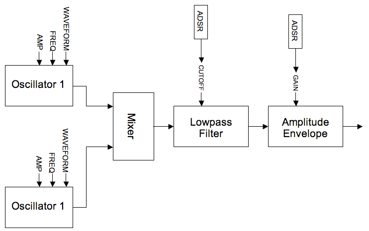
The first example represents perhaps the classic idea of subtractive synthesis: a simple two oscillator synth filtered using a single resonant lowpass filter. Many of the ideas used in this example have been inspired by the design of the Minimoog synthesizer (1970) and other similar instruments.
Each oscillator can describe either a sawtooth, PWM waveform (i.e. square - pulse etc.) or white noise and each oscillator can be transposed in octaves or in cents with respect to a fundamental pitch. The two oscillators are mixed and then passed through a 4-pole / 24dB per octave resonant lowpass filter. The opcode 'moogladder' is chosen on account of its authentic vintage character. The cutoff frequency of the filter is modulated using an ADSR-style (attack-decay-sustain-release) envelope facilitating the creation of dynamic, evolving spectra. Finally the sound output of the filter is shaped by an ADSR amplitude envelope. Waveforms such as sawtooths and square waves offer rich sources for subtractive synthesis as they contains a lot of sound energy across a wide range of frequencies - it could be said that white noise offers the richest sound source containing, as it does, energy at every frequency. A sine wave would offer a very poor source for subtractive synthesis as it contains energy at only one frequency. Other Csound opcodes that might provide rich sources are the buzz and gbuzz opcodes and the GEN09, GEN10, GEN11 and GEN19 GEN routines.
As this instrument is suggestive of a performance instrument controlled via MIDI, this has been partially implemented. Through the use of Csound's MIDI interoperability opcode, mididefault, the instrument can be operated from the score or from a MIDI keyboard. If a MIDI note is received, suitable default p-field values are substituted for the missing p-fields. MIDI controller 1 can be used to control the global cutoff frequency for the filter.
A schematic for this instrument is shown below:
EXAMPLE 04B01_Subtractive_Midi.csd
<CsoundSynthesizer>

<CsOptions>
-odac -Ma
</CsOptions>

<CsInstruments>
sr = 44100
ksmps = 4
nchnls = 2
0dbfs = 1

initc7 1,1,0.8                 ;set initial controller position

prealloc 1, 10

   instr 1
iNum   notnum                  ;read in midi note number
iCF    ctrl7        1,1,0.1,14 ;read in midi controller 1

; set up default p-field values for midi activated notes
       mididefault  iNum, p4   ;pitch (note number)
       mididefault  0.3, p5    ;amplitude 1
       mididefault  2, p6      ;type 1
       mididefault  0.5, p7    ;pulse width 1
       mididefault  0, p8      ;octave disp. 1
       mididefault  0, p9      ;tuning disp. 1
       mididefault  0.3, p10   ;amplitude 2
       mididefault  1, p11     ;type 2
       mididefault  0.5, p12   ;pulse width 2
       mididefault  -1, p13    ;octave displacement 2
       mididefault  20, p14    ;tuning disp. 2
       mididefault  iCF, p15   ;filter cutoff freq
       mididefault  0.01, p16  ;filter env. attack time
       mididefault  1, p17     ;filter env. decay time
       mididefault  0.01, p18  ;filter env. sustain level
       mididefault  0.1, p19   ;filter release time
       mididefault  0.3, p20   ;filter resonance
       mididefault  0.01, p21  ;amp. env. attack
       mididefault  0.1, p22   ;amp. env. decay.
       mididefault  1, p23     ;amp. env. sustain
       mididefault  0.01, p24  ;amp. env. release

; asign p-fields to variables
iCPS   =            cpsmidinn(p4) ;convert from note number to cps
kAmp1  =            p5
iType1 =            p6
kPW1   =            p7
kOct1  =            octave(p8) ;convert from octave displacement to multiplier
kTune1 =            cent(p9)   ;convert from cents displacement to multiplier
kAmp2  =            p10
iType2 =            p11
kPW2   =            p12
kOct2  =            octave(p13)
kTune2 =            cent(p14)
iCF    =            p15
iFAtt  =            p16
iFDec  =            p17
iFSus  =            p18
iFRel  =            p19
kRes   =            p20
iAAtt  =            p21
iADec  =            p22
iASus  =            p23
iARel  =            p24

;oscillator 1
;if type is sawtooth or square...
if iType1==1||iType1==2 then
 ;...derive vco2 'mode' from waveform type
 iMode1 = (iType1=1?0:2)
 aSig1  vco2   kAmp1,iCPS*kOct1*kTune1,iMode1,kPW1;VCO audio oscillator
else                                   ;otherwise...
 aSig1  noise  kAmp1, 0.5              ;...generate white noise
endif

;oscillator 2 (identical in design to oscillator 1)
if iType2==1||iType2==2 then
 iMode2  =  (iType2=1?0:2)
 aSig2  vco2   kAmp2,iCPS*kOct2*kTune2,iMode2,kPW2
else
  aSig2 noise  kAmp2,0.5
endif

;mix oscillators
aMix       sum          aSig1,aSig2
;lowpass filter
kFiltEnv   expsegr      0.0001,iFAtt,iCPS*iCF,iFDec,iCPS*iCF*iFSus,iFRel,0.0001
aOut       moogladder   aMix, kFiltEnv, kRes

;amplitude envelope
aAmpEnv    expsegr      0.0001,iAAtt,1,iADec,iASus,iARel,0.0001
aOut       =            aOut*aAmpEnv
           outs         aOut,aOut
  endin
</CsInstruments>

<CsScore>
;p4  = oscillator frequency
;oscillator 1
;p5  = amplitude
;p6  = type (1=sawtooth,2=square-PWM,3=noise)
;p7  = PWM (square wave only)
;p8  = octave displacement
;p9  = tuning displacement (cents)
;oscillator 2
;p10 = amplitude
;p11 = type (1=sawtooth,2=square-PWM,3=noise)
;p12 = pwm (square wave only)
;p13 = octave displacement
;p14 = tuning displacement (cents)
;global filter envelope
;p15 = cutoff
;p16 = attack time
;p17 = decay time
;p18 = sustain level (fraction of cutoff)
;p19 = release time
;p20 = resonance
;global amplitude envelope
;p21 = attack time
;p22 = decay time
;p23 = sustain level
;p24 = release time
; p1 p2 p3  p4 p5  p6 p7   p8 p9  p10 p11 p12 p13
;p14 p15 p16  p17  p18  p19 p20 p21  p22 p23 p24
i 1  0  1   50 0   2  .5   0  -5  0   2   0.5 0   \
 5   12  .01  2    .01  .1  0   .005 .01 1   .05
i 1  +  1   50 .2  2  .5   0  -5  .2  2   0.5 0   \
 5   1   .01  1    .1   .1  .5  .005 .01 1   .05
i 1  +  1   50 .2  2  .5   0  -8  .2  2   0.5 0   \
 8   3   .01  1    .1   .1  .5  .005 .01 1   .05
i 1  +  1   50 .2  2  .5   0  -8  .2  2   0.5 -1  \
 8   7  .01   1    .1   .1  .5  .005 .01 1   .05
i 1  +  3   50 .2  1  .5   0  -10 .2  1   0.5 -2  \
 10  40  .01  3    .001 .1  .5  .005 .01 1   .05
i 1  +  10  50 1   2  .01  -2 0   .2  3   0.5 0   \
 0   40  5    5    .001 1.5 .1  .005 .01 1   .05

f 0 3600
e
</CsScore>

</CsoundSynthesizer>
Simulation of Timbres from a Noise Source
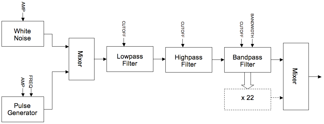
The next example makes extensive use of bandpass filters arranged in parallel to filter white noise. The bandpass filter bandwidths are narrowed to the point where almost pure tones are audible. The crucial difference is that the noise source always induces instability in the amplitude and frequency of tones produced - it is this quality that makes this sort of subtractive synthesis sound much more organic than an additive synthesis equivalent. If the bandwidths are widened, then more of the characteristic of the noise source comes through and the tone becomes 'airier' and less distinct; if the bandwidths are narrowed, the resonating tones become clearer and steadier. By varying the bandwidths interesting metamorphoses of the resultant sound are possible.
22 reson filters are used for the bandpass filters on account of their ability to ring and resonate as their bandwidth narrows. Another reason for this choice is the relative CPU economy of the reson filter, a not insignificant concern as so many of them are used. The frequency ratios between the 22 parallel filters are derived from analysis of a hand bell, the data was found in the appendix of the Csound manual here. Obviously with so much repetition of similar code, some sort of abstraction would be a good idea (perhaps through a UDO or by using a macro), but here, and for the sake of clarity, it is left unabstracted.
In addition to the white noise as a source, noise impulses are also used as a sound source (via the 'mpulse' opcode). The instrument will automatically and randomly slowly crossfade between these two sound sources.
A lowpass and highpass filter are inserted in series before the parallel bandpass filters to shape the frequency spectrum of the source sound. Csound's butterworth filters butlp and buthp are chosen for this task on account of their steep cutoff slopes and minimal ripple at the cutoff frequency.
The outputs of the reson filters are sent alternately to the left and right outputs in order to create a broad stereo effect.
This example makes extensive use of the 'rspline' opcode, a generator of random spline functions, to slowly undulate the many input parameters. The orchestra is self generative in that instrument 1 repeatedly triggers note events in instrument 2 and the extensive use of random functions means that the results will continually evolve as the orchestra is allowed to perform.
A flow diagram for this instrument is shown below:
EXAMPLE 04B02_Subtractive_timbres.csd
<CsoundSynthesizer>

<CsOptions>
-odac
</CsOptions>

<CsInstruments>
;Example written by Iain McCurdy

sr = 44100
ksmps = 16
nchnls = 2
0dbfs = 1

  instr 1 ; triggers notes in instrument 2 with randomised p-fields
krate  randomi 0.2,0.4,0.1   ;rate of note generation
ktrig  metro  krate          ;triggers used by schedkwhen
koct   random 5,12           ;fundemental pitch of synth note
kdur   random 15,30          ;duration of note
schedkwhen ktrig,0,0,2,0,kdur,cpsoct(koct) ;trigger a note in instrument 2
  endin

  instr 2 ; subtractive synthesis instrument
aNoise  pinkish  1                  ;a noise source sound: pink noise
kGap    rspline  0.3,0.05,0.2,2     ;time gap between impulses
aPulse  mpulse   15, kGap           ;a train of impulses
kCFade  rspline  0,1,0.1,1          ;crossfade point between noise and impulses
aInput  ntrpol   aPulse,aNoise,kCFade;implement crossfade

; cutoff frequencies for low and highpass filters
kLPF_CF  rspline  13,8,0.1,0.4
kHPF_CF  rspline  5,10,0.1,0.4
; filter input sound with low and highpass filters in series -
; - done twice per filter in order to sharpen cutoff slopes
aInput    butlp    aInput, cpsoct(kLPF_CF)
aInput    butlp    aInput, cpsoct(kLPF_CF)
aInput    buthp    aInput, cpsoct(kHPF_CF)
aInput    buthp    aInput, cpsoct(kHPF_CF)

kcf     rspline  p4*1.05,p4*0.95,0.01,0.1 ; fundemental
; bandwidth for each filter is created individually as a random spline function
kbw1    rspline  0.00001,10,0.2,1
kbw2    rspline  0.00001,10,0.2,1
kbw3    rspline  0.00001,10,0.2,1
kbw4    rspline  0.00001,10,0.2,1
kbw5    rspline  0.00001,10,0.2,1
kbw6    rspline  0.00001,10,0.2,1
kbw7    rspline  0.00001,10,0.2,1
kbw8    rspline  0.00001,10,0.2,1
kbw9    rspline  0.00001,10,0.2,1
kbw10   rspline  0.00001,10,0.2,1
kbw11   rspline  0.00001,10,0.2,1
kbw12   rspline  0.00001,10,0.2,1
kbw13   rspline  0.00001,10,0.2,1
kbw14   rspline  0.00001,10,0.2,1
kbw15   rspline  0.00001,10,0.2,1
kbw16   rspline  0.00001,10,0.2,1
kbw17   rspline  0.00001,10,0.2,1
kbw18   rspline  0.00001,10,0.2,1
kbw19   rspline  0.00001,10,0.2,1
kbw20   rspline  0.00001,10,0.2,1
kbw21   rspline  0.00001,10,0.2,1
kbw22   rspline  0.00001,10,0.2,1

imode   =        0 ; amplitude balancing method used by the reson filters
a1      reson    aInput, kcf*1,               kbw1, imode
a2      reson    aInput, kcf*1.0019054878049, kbw2, imode
a3      reson    aInput, kcf*1.7936737804878, kbw3, imode
a4      reson    aInput, kcf*1.8009908536585, kbw4, imode
a5      reson    aInput, kcf*2.5201981707317, kbw5, imode
a6      reson    aInput, kcf*2.5224085365854, kbw6, imode
a7      reson    aInput, kcf*2.9907012195122, kbw7, imode
a8      reson    aInput, kcf*2.9940548780488, kbw8, imode
a9      reson    aInput, kcf*3.7855182926829, kbw9, imode
a10     reson    aInput, kcf*3.8061737804878, kbw10,imode
a11     reson    aInput, kcf*4.5689024390244, kbw11,imode
a12     reson    aInput, kcf*4.5754573170732, kbw12,imode
a13     reson    aInput, kcf*5.0296493902439, kbw13,imode
a14     reson    aInput, kcf*5.0455030487805, kbw14,imode
a15     reson    aInput, kcf*6.0759908536585, kbw15,imode
a16     reson    aInput, kcf*5.9094512195122, kbw16,imode
a17     reson    aInput, kcf*6.4124237804878, kbw17,imode
a18     reson    aInput, kcf*6.4430640243902, kbw18,imode
a19     reson    aInput, kcf*7.0826219512195, kbw19,imode
a20     reson    aInput, kcf*7.0923780487805, kbw20,imode
a21     reson    aInput, kcf*7.3188262195122, kbw21,imode
a22     reson    aInput, kcf*7.5551829268293, kbw22,imode

; amplitude control for each filter output
kAmp1    rspline  0, 1, 0.3, 1
kAmp2    rspline  0, 1, 0.3, 1
kAmp3    rspline  0, 1, 0.3, 1
kAmp4    rspline  0, 1, 0.3, 1
kAmp5    rspline  0, 1, 0.3, 1
kAmp6    rspline  0, 1, 0.3, 1
kAmp7    rspline  0, 1, 0.3, 1
kAmp8    rspline  0, 1, 0.3, 1
kAmp9    rspline  0, 1, 0.3, 1
kAmp10   rspline  0, 1, 0.3, 1
kAmp11   rspline  0, 1, 0.3, 1
kAmp12   rspline  0, 1, 0.3, 1
kAmp13   rspline  0, 1, 0.3, 1
kAmp14   rspline  0, 1, 0.3, 1
kAmp15   rspline  0, 1, 0.3, 1
kAmp16   rspline  0, 1, 0.3, 1
kAmp17   rspline  0, 1, 0.3, 1
kAmp18   rspline  0, 1, 0.3, 1
kAmp19   rspline  0, 1, 0.3, 1
kAmp20   rspline  0, 1, 0.3, 1
kAmp21   rspline  0, 1, 0.3, 1
kAmp22   rspline  0, 1, 0.3, 1

; left and right channel mixes are created using alternate filter outputs.
; This shall create a stereo effect.
aMixL    sum      a1*kAmp1,a3*kAmp3,a5*kAmp5,a7*kAmp7,a9*kAmp9,a11*kAmp11,\
                        a13*kAmp13,a15*kAmp15,a17*kAmp17,a19*kAmp19,a21*kAmp21
aMixR    sum      a2*kAmp2,a4*kAmp4,a6*kAmp6,a8*kAmp8,a10*kAmp10,a12*kAmp12,\
                        a14*kAmp14,a16*kAmp16,a18*kAmp18,a20*kAmp20,a22*kAmp22

kEnv     linseg   0, p3*0.5, 1,p3*0.5,0,1,0       ; global amplitude envelope
outs   (aMixL*kEnv*0.00008), (aMixR*kEnv*0.00008) ; audio sent to outputs
  endin

</CsInstruments>

<CsScore>
i 1 0 3600  ; instrument 1 (note generator) plays for 1 hour
e
</CsScore>

</CsoundSynthesizer>
Vowel-Sound Emulation Using Bandpass Filtering
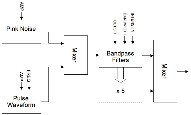
The final example in this section uses precisely tuned bandpass filters, to simulate the sound of the human voice expressing vowel sounds. Spectral resonances in this context are often referred to as 'formants'. Five formants are used to simulate the effect of the human mouth and head as a resonating (and therefore filtering) body. The filter data for simulating the vowel sounds A,E,I,O and U as expressed by a bass, tenor, counter-tenor, alto and soprano voice were found in the appendix of the Csound manual here. Bandwidth and intensity (dB) information is also needed to accurately simulate the various vowel sounds.
reson filters are again used but butbp and others could be equally valid choices.
Data is stored in GEN07 linear break point function tables, as this data is read by k-rate line functions we can interpolate and therefore morph between different vowel sounds during a note.
The source sound for the filters comes from either a pink noise generator or a pulse waveform. The pink noise source could be used if the emulation is to be that of just the breath whereas the pulse waveform provides a decent approximation of the human vocal chords buzzing. This instrument can however morph continuously between these two sources.
A flow diagram for this instrument is shown below:
EXAMPLE 04B03_Subtractive_vowels.csd
<CsoundSynthesizer>

<CsOptions>
-odac
</CsOptions>

<CsInstruments>
;example by Iain McCurdy

sr = 44100
ksmps = 16
nchnls = 2
0dbfs = 1

;FUNCTION TABLES STORING DATA FOR VARIOUS VOICE FORMANTS

;BASS
giBF1 ftgen 0, 0, -5, -2, 600,   400, 250,   400,  350
giBF2 ftgen 0, 0, -5, -2, 1040, 1620, 1750,  750,  600
giBF3 ftgen 0, 0, -5, -2, 2250, 2400, 2600, 2400, 2400
giBF4 ftgen 0, 0, -5, -2, 2450, 2800, 3050, 2600, 2675
giBF5 ftgen 0, 0, -5, -2, 2750, 3100, 3340, 2900, 2950

giBDb1 ftgen 0, 0, -5, -2,   0,	  0,   0,   0,   0
giBDb2 ftgen 0, 0, -5, -2,  -7,	-12, -30, -11, -20
giBDb3 ftgen 0, 0, -5, -2,  -9,	 -9, -16, -21, -32
giBDb4 ftgen 0, 0, -5, -2,  -9,	-12, -22, -20, -28
giBDb5 ftgen 0, 0, -5, -2, -20,	-18, -28, -40, -36

giBBW1 ftgen 0, 0, -5, -2,  60,  40,  60,  40,  40
giBBW2 ftgen 0, 0, -5, -2,  70,  80,  90,  80,  80
giBBW3 ftgen 0, 0, -5, -2, 110, 100, 100, 100, 100
giBBW4 ftgen 0, 0, -5, -2, 120, 120, 120, 120, 120
giBBW5 ftgen 0, 0, -5, -2, 130, 120, 120, 120, 120

;TENOR
giTF1 ftgen 0, 0, -5, -2,  650,  400,  290,  400,  350
giTF2 ftgen 0, 0, -5, -2, 1080, 1700, 1870,  800,  600
giTF3 ftgen 0, 0, -5, -2, 2650,	2600, 2800, 2600, 2700
giTF4 ftgen 0, 0, -5, -2, 2900,	3200, 3250, 2800, 2900
giTF5 ftgen 0, 0, -5, -2, 3250,	3580, 3540, 3000, 3300

giTDb1 ftgen 0, 0, -5, -2,   0,   0,   0,   0,   0
giTDb2 ftgen 0, 0, -5, -2,  -6, -14, -15, -10, -20
giTDb3 ftgen 0, 0, -5, -2,  -7, -12, -18, -12, -17
giTDb4 ftgen 0, 0, -5, -2,  -8, -14, -20, -12, -14
giTDb5 ftgen 0, 0, -5, -2, -22, -20, -30, -26, -26

giTBW1 ftgen 0, 0, -5, -2,  80,	 70,  40,  40,  40
giTBW2 ftgen 0, 0, -5, -2,  90,	 80,  90,  80,  60
giTBW3 ftgen 0, 0, -5, -2, 120,	100, 100, 100, 100
giTBW4 ftgen 0, 0, -5, -2, 130,	120, 120, 120, 120
giTBW5 ftgen 0, 0, -5, -2, 140,	120, 120, 120, 120

;COUNTER TENOR
giCTF1 ftgen 0, 0, -5, -2,  660,  440,  270,  430,  370
giCTF2 ftgen 0, 0, -5, -2, 1120, 1800, 1850,  820,  630
giCTF3 ftgen 0, 0, -5, -2, 2750, 2700, 2900, 2700, 2750
giCTF4 ftgen 0, 0, -5, -2, 3000, 3000, 3350, 3000, 3000
giCTF5 ftgen 0, 0, -5, -2, 3350, 3300, 3590, 3300, 3400

giTBDb1 ftgen 0, 0, -5, -2,   0,   0,   0,   0,   0
giTBDb2 ftgen 0, 0, -5, -2,  -6, -14, -24, -10, -20
giTBDb3 ftgen 0, 0, -5, -2, -23, -18, -24, -26, -23
giTBDb4 ftgen 0, 0, -5, -2, -24, -20, -36, -22, -30
giTBDb5 ftgen 0, 0, -5, -2, -38, -20, -36, -34, -30

giTBW1 ftgen 0, 0, -5, -2, 80,   70,  40,  40,  40
giTBW2 ftgen 0, 0, -5, -2, 90,   80,  90,  80,  60
giTBW3 ftgen 0, 0, -5, -2, 120, 100, 100, 100, 100
giTBW4 ftgen 0, 0, -5, -2, 130, 120, 120, 120, 120
giTBW5 ftgen 0, 0, -5, -2, 140, 120, 120, 120, 120

;ALTO
giAF1 ftgen 0, 0, -5, -2,  800,  400,  350,  450,  325
giAF2 ftgen 0, 0, -5, -2, 1150, 1600, 1700,  800,  700
giAF3 ftgen 0, 0, -5, -2, 2800, 2700, 2700, 2830, 2530
giAF4 ftgen 0, 0, -5, -2, 3500, 3300, 3700, 3500, 2500
giAF5 ftgen 0, 0, -5, -2, 4950, 4950, 4950, 4950, 4950

giADb1 ftgen 0, 0, -5, -2,   0,   0,   0,   0,   0
giADb2 ftgen 0, 0, -5, -2,  -4, -24, -20,  -9, -12
giADb3 ftgen 0, 0, -5, -2, -20, -30, -30, -16, -30
giADb4 ftgen 0, 0, -5, -2, -36, -35, -36, -28, -40
giADb5 ftgen 0, 0, -5, -2, -60, -60, -60, -55, -64

giABW1 ftgen 0, 0, -5, -2, 50,   60,  50,  70,  50
giABW2 ftgen 0, 0, -5, -2, 60,   80, 100,  80,  60
giABW3 ftgen 0, 0, -5, -2, 170, 120, 120, 100, 170
giABW4 ftgen 0, 0, -5, -2, 180, 150, 150, 130, 180
giABW5 ftgen 0, 0, -5, -2, 200, 200, 200, 135, 200

;SOPRANO
giSF1 ftgen 0, 0, -5, -2,  800,  350,  270,  450,  325
giSF2 ftgen 0, 0, -5, -2, 1150, 2000, 2140,  800,  700
giSF3 ftgen 0, 0, -5, -2, 2900, 2800, 2950, 2830, 2700
giSF4 ftgen 0, 0, -5, -2, 3900, 3600, 3900, 3800, 3800
giSF5 ftgen 0, 0, -5, -2, 4950, 4950, 4950, 4950, 4950

giSDb1 ftgen 0, 0, -5, -2,   0,   0,   0,   0,   0
giSDb2 ftgen 0, 0, -5, -2,  -6, -20, -12, -11, -16
giSDb3 ftgen 0, 0, -5, -2, -32, -15, -26, -22, -35
giSDb4 ftgen 0, 0, -5, -2, -20, -40, -26, -22, -40
giSDb5 ftgen 0, 0, -5, -2, -50, -56, -44, -50, -60

giSBW1 ftgen 0, 0, -5, -2,  80,  60,  60,  70,  50
giSBW2 ftgen 0, 0, -5, -2,  90,  90,  90,  80,  60
giSBW3 ftgen 0, 0, -5, -2, 120, 100, 100, 100, 170
giSBW4 ftgen 0, 0, -5, -2, 130, 150, 120, 130, 180
giSBW5 ftgen 0, 0, -5, -2, 140, 200, 120, 135, 200

instr 1
  kFund    expon     p4,p3,p5               ; fundamental
  kVow     line      p6,p3,p7               ; vowel select
  kBW      line      p8,p3,p9               ; bandwidth factor
  iVoice   =         p10                    ; voice select
  kSrc     line      p11,p3,p12             ; source mix

  aNoise   pinkish   3                      ; pink noise
  aVCO     vco2      1.2,kFund,2,0.02       ; pulse tone
  aInput   ntrpol    aVCO,aNoise,kSrc       ; input mix

  ; read formant cutoff frequenies from tables
  kCF1     tablei    kVow*5,giBF1+(iVoice*15)
  kCF2     tablei    kVow*5,giBF1+(iVoice*15)+1
  kCF3     tablei    kVow*5,giBF1+(iVoice*15)+2
  kCF4     tablei    kVow*5,giBF1+(iVoice*15)+3
  kCF5     tablei    kVow*5,giBF1+(iVoice*15)+4
  ; read formant intensity values from tables
  kDB1     tablei    kVow*5,giBF1+(iVoice*15)+5
  kDB2     tablei    kVow*5,giBF1+(iVoice*15)+6
  kDB3     tablei    kVow*5,giBF1+(iVoice*15)+7
  kDB4     tablei    kVow*5,giBF1+(iVoice*15)+8
  kDB5     tablei    kVow*5,giBF1+(iVoice*15)+9
  ; read formant bandwidths from tables
  kBW1     tablei    kVow*5,giBF1+(iVoice*15)+10
  kBW2     tablei    kVow*5,giBF1+(iVoice*15)+11
  kBW3     tablei    kVow*5,giBF1+(iVoice*15)+12
  kBW4     tablei    kVow*5,giBF1+(iVoice*15)+13
  kBW5     tablei    kVow*5,giBF1+(iVoice*15)+14
  ; create resonant formants byt filtering source sound
  aForm1   reson     aInput, kCF1, kBW1*kBW, 1     ; formant 1
  aForm2   reson     aInput, kCF2, kBW2*kBW, 1     ; formant 2
  aForm3   reson     aInput, kCF3, kBW3*kBW, 1     ; formant 3
  aForm4   reson     aInput, kCF4, kBW4*kBW, 1     ; formant 4
  aForm5   reson     aInput, kCF5, kBW5*kBW, 1     ; formant 5

  ; formants are mixed and multiplied both by intensity values derived from tables and by the on-screen gain controls for each formant
  aMix     sum       aForm1*ampdbfs(kDB1),aForm2*ampdbfs(kDB2),aForm3*ampdbfs(kDB3),aForm4*ampdbfs(kDB4),aForm5*ampdbfs(kDB5)
  kEnv     linseg    0,3,1,p3-6,1,3,0     ; an amplitude envelope
           outs      aMix*kEnv, aMix*kEnv ; send audio to outputs
endin

</CsInstruments>

<CsScore>
; p4 = fundemental begin value (c.p.s.)
; p5 = fundemental end value
; p6 = vowel begin value (0 - 1 : a e i o u)
; p7 = vowel end value
; p8 = bandwidth factor begin (suggested range 0 - 2)
; p9 = bandwidth factor end
; p10 = voice (0=bass; 1=tenor; 2=counter_tenor; 3=alto; 4=soprano)
; p11 = input source begin (0 - 1 : VCO - noise)
; p12 = input source end

;         p4  p5  p6  p7  p8  p9 p10 p11  p12
i 1 0  10 50  100 0   1   2   0  0   0    0
i 1 8  .  78  77  1   0   1   0  1   0    0
i 1 16 .  150 118 0   1   1   0  2   1    1
i 1 24 .  200 220 1   0   0.2 0  3   1    0
i 1 32 .  400 800 0   1   0.2 0  4   0    1
e
</CsScore>

</CsoundSynthesizer>
Conclusion
These examples have hopefully demonstrated the strengths of subtractive synthesis in its simplicity, intuitive operation and its ability to create organic sounding timbres. Further research could explore Csound's other filter opcodes including vcomb, wguide1, wguide2, mode and the more esoteric phaser1, phaser2 and resony.